Using TVD Connectors to Query Averaged Spatial Rainfall
It is possible to create one or more TVD connectors with polygon geometry which will contain the averaged spatial rainfall results for a given simulation, using rainfall data from spatial TSDBs.
This can be useful, for example, if you want to know how much rainfall, which is approaching an existing network but not yet falling on it, fell on average (over time) over an area which is located outside the existing network.
Once you have run the simulation, you can display a graph and grid of the result.
An overview of using a TVD connector polygon to query averaged spatial rainfall is outlined below:
- Ensure that the relevant network is opened in the GeoPlan.
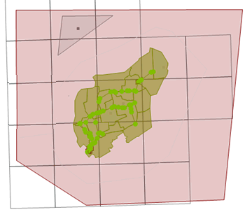
- On the GeoPlan, create a new polygon (TVD connector) object, which covers the area for which the simulation is to be run. The polygon can exist outside of the network but must be within the spatial rainfall area (the gridded, radar cell boundaries area) as shown in the following example:
If the existing network contains a spatial rain zone, then the polygon (TVD connector) being created must be enclosed by a spatial rain zone (either the original spatial rain zone or a new one). A spatial rain zone is used to define where the rainfall calculations take place – if there is a spatial TSDB with a large area of gridded rainfall then the calculations may take a long time. The spatial rain zone can be used to narrow the calculations down to only the area you are interested in. If there is not a spatial rain zone then the whole of the spatial rainfall is used. If there is a spatial rain zone then only that area of spatial rainfall is used. If your TVD connector falls out of this area, then you need another spatial rain zone to make sure that it can use the spatial rainfall.
- Ensure that Type is set to TVD connector in the Create New Object dialog and click OK.
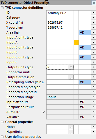
The object properties sheet, for the newly created TVD connector, is automatically displayed on the left part of the main window. The ID, X coord, Y coord and Area fields are automatically filled-in, and the Connection usage is automatically set to Input (default).
- Ensure that the Output units type field in the TVD connector's properties is set to R (rainfall intensity). No other properties should be specified.
- If you want to add another TVD connector for querying the averaged spatial rainfall, then repeat Steps 2 to 4.
- Validate the network.
The network should validate without any errors or warnings related to the TVD connector(s).
Note that a warning message will still be issued if the new TVD connector's Output units type is not set to R.
- Run the simulation, and ensure that you specify the current network and use the spatial TSDB that covers the area that includes the newly created TVD connector(s).
When the simulation has run successfully, you can view the results as a graph or grid.
One way you can view the average spatial rainfall for the area enclosed by the TVD connector(s) is to:
- Open the simulation on the GeoPlan.
- Click on the
 (Graph Pick) toolbar button.
 - Select the TVD connector.
A graph showing the averaged spatial rainfall result for the TVD connector polygon will be displayed.
If required, you can compare this result with a graph of the spatial rainfall profile for the grid cell(s) which cover the same area as the polygon. Create another TVD connector polygon that exactly matches the shape of a subcatchment, ensure that the subcatchment Use area-averaged rain parameter is checked (otherwise you may get a slightly different result, as the subcatchment will get its rainfall from the rainfall grid cell which covers the centroid of the subcatchment rather than an area averaged result from all the rainfall grid cells which cover it), and then run the simulation. The TVD connector rainfall result should match the subcatchment rainfall result.


